
Industrial Workshop Lab Equipments
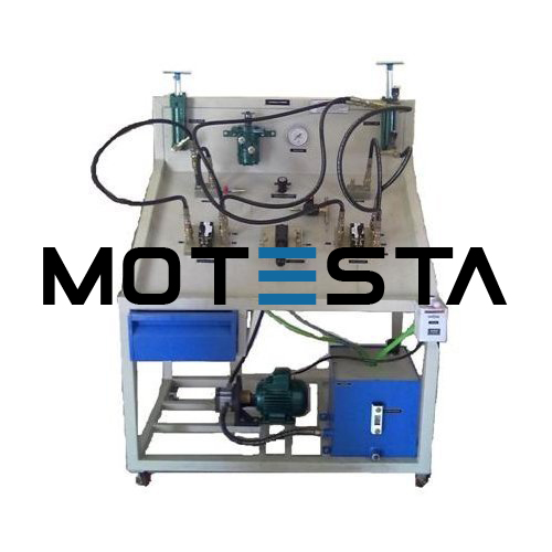
Electro-Hydraulic Trainer Kit
Model No – NID-25-01-19-0020
Electro Hydraulic Circuit Trainer outlines the basic Principle of Hydraulic Control System, Hydraulic Control System Components and its applications using electronic proximity position sensor and electro-mechanical actuators (solenoid valves).
TECHNICAL SPECIFICATION
- Relay Module: – 4 Relays, 24V DC supply, 2 NO/NC contacts, panel mounting type.
- Single Acting Cylinder: – Bore: 40 mm, Stroke: 75mm/100mm, Mounting: Foot.
- Double Acting Cylinder: – Bore: 40 mm, Stroke: 75mm/100mm, Mounting: Foot
- Solenoid Valve: – 2 Nos, 4/3 way, ¼”, 230VAC and 4/2 way, ¼”, 230 VAC.
- Meter-in Circuit and Meter Out Circuit
- Bleed-off Circuit
- Pulley Arrangement to carry load applied to the actuator, i.e., Double Acting Cylinder (Optional)
- Pressure Relief Valve:- ¼”, 60 Kg/cm2
- Flow Control Valve: – ¼” (F), Square Body.
- Block Manifold: – ¼”, 4 ways.
- Male Connector: – ¼”Quick Release Couplings
- Indicator: 24 VDC Operated.
- Proximity Sensors: – 4 nos. Type: Inductive 2 wires, Diameter: 18 mm, Sensing Distance: 5 mm.
- Pressure Gauge: – 100 Kg/cm2, Dial Size: 100 mm.
- Hydraulic Motor (Optional) 3 LPM, Flange mounting type.
- Hydraulic Accumulator (Optional) Capacity : 0.075 Ltrs, mWP bar: 250 bar
- Weight: 0.62 Kg, Connection: 1/2″ BSP
- Pressure sequence valve (optional):- ¼” (F), Square Body, 60kg/cm^2.
- Oil Hydraulic power pack: – MS Powder Coated Oil Tank, Capacity: 25 Litters. with Oil Level Indicator, Gear Pump: 3-5 LPM, 40-70 Bar, Breather, Oil filter and suction, Electric Motor: Single Phase, 1/2 HP/ 1HP, 230VAC / 3 Phase, 1/2 HP/ 1 HP, 415V AC with DOL starter.
- Hydraulic Hoses: – 10nos.
- Transverse and Feed Circuit (Optional)
FEATURES
- Compact Ergonomic Design.
- User Friendly, Self Explanatory Systems.
- Leak proof Safety Measures, sturdy piping and Robust Construction.
- Training Manuals mimic Charts for Operation Ease.
- System Frame with Caster Wheel Arrangement for ease in movement.
- M.S. powder coated cubical plant with standard Instrument Mountings.
- Inbuilt Safety Measures to avoid improper usage.
SYSTEM SPECIFICATIONS
- Wall mounting assemblies of hydraulic actuator and self-reciprocating cylinder.
- Single acting cylinder (bore diameter: 40mm, stroke length: 75/ 100mm)
- Double acting cylinder (bore diameter: 40mm, stroke length: 75/ 100mm)
- Hydraulic motor (optional), Solenoid Valves (electro-hydraulic), Limit Switches.
- Proximity type sensors (electro-hydraulic),
- QRC Couplings provided Tubing /hose pipes for circulation of pressure.
- Manifold for distribution.
- Oil Hydraulic power pack for power supply.
- Optional components are available to allow fault operation and diagnosis training.
- RANGE OF EXPERIMENTS
- Study of pressure control.
- Study of direction control.
- Study of fundamental principles of Hydraulics and its applications.
- Study of Meter-in circuit, Meter-out circuit and Bleed-off circuit.
- Study of flow control.
- Study of hydraulic valves.
- Study of cylinder control.
- Study of power pack control characteristics.
- Study of hydraulic Motor (optional).
- Study of Hydraulic Accumulator (optional).
- Study of sequencing of two cylinders using sequence valve (optional).
- Study of electro-hydraulic control.
- Study of sequencing operation of two cylinders using electro-hydraulic components